MaxxFan Brushless Retrofit
The MaxxFan is the default roof fan in camper vans, and its brushed motor is the weak spot: it gets loud and squeaky, and cleaning the brushes only buys time. This retrofit keeps the fan’s housing, 12 in blade and powered lid, and replaces the motor with a 50 W brushless one run by field-oriented control (FOC), which is close to silent.
It’s run by a knob and a direction switch, which I like better than the stock button pad. Turn the knob to its click to close the lid, just past it to open the lid for a breeze, and further up for fan speed. A phone page on the van’s Wi-Fi does the same (no app, no cloud), and the knob still runs the fan if the controller ever dies.
How it’s built
- Motor: StepperOnline 57BYA54-12-01, 12 V, 50 W brushless. Its hall sensors aren’t used.
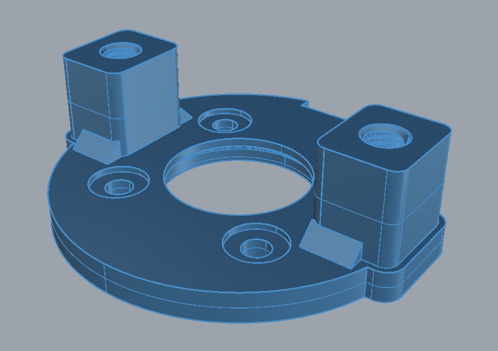
- Mount: a 3D-printed PETG cage bolts the motor to the fan’s two original motor ears and puts the blade back where it was. A shaft coupler and an 8 mm dowel extend the shaft to the blade hub.
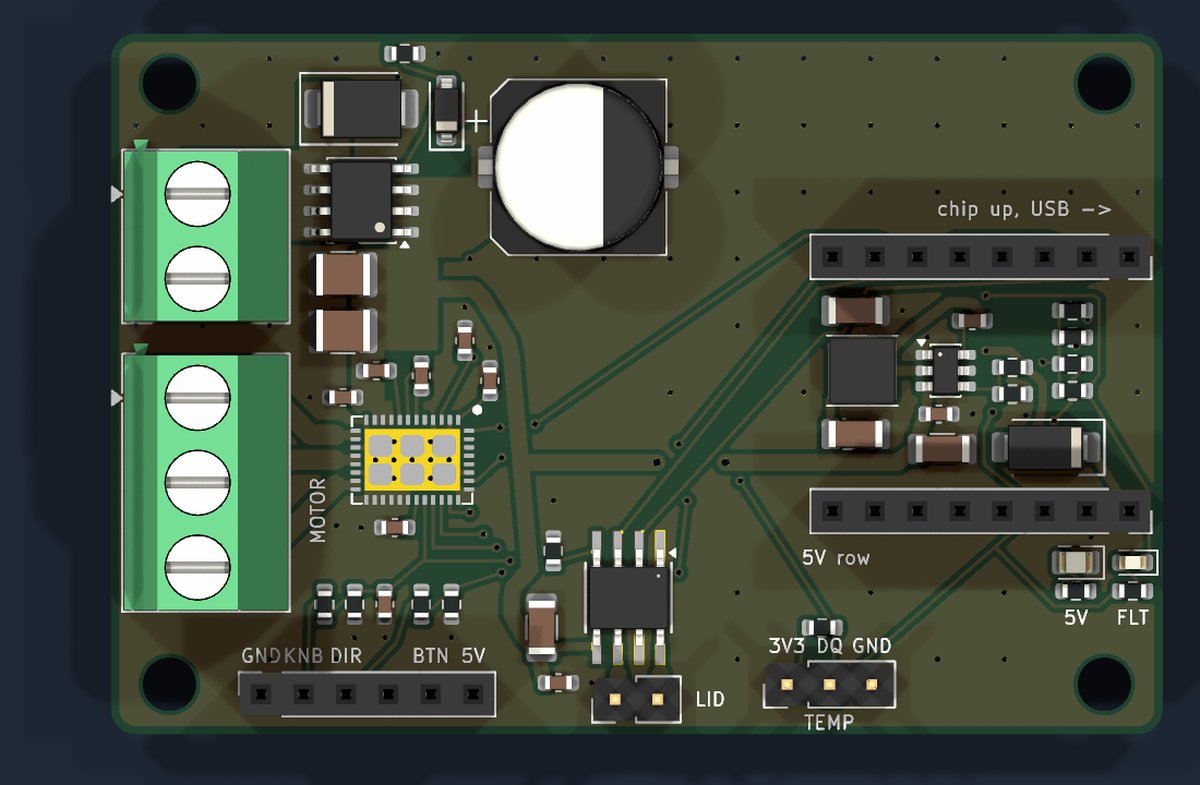
- Board: one 63 x 42 mm board does all of it. A TI MCF8316D runs the fan motor, a DRV8871 runs the lid motor, a buck converter makes 5 V from the van’s 12 V (with reverse-polarity and surge protection), and an ESP32-C3 SuperMini plugs in on top and sets everything up. JLCPCB makes it and fits the small parts; you solder the connectors.
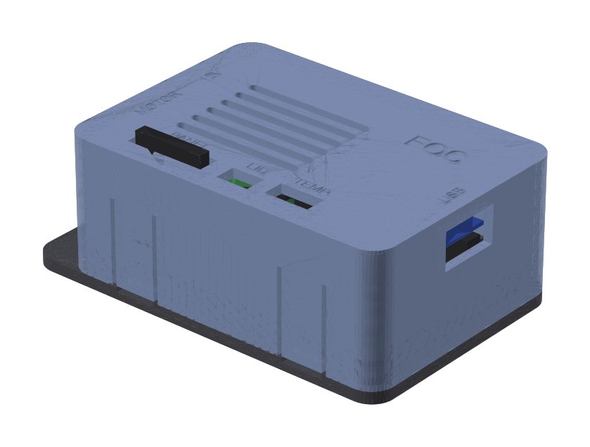
- Controller box: a printed base sticks to the fan’s control plate where the stock circuit board was, the board screws to it, and a cover snaps on over it with slots for the plugs.
- Firmware: Arduino on the ESP32-C3: the phone page, lid calibration, live motor graphs and updates over Wi-Fi. Open source on GitHub.
The phone page
The board serves its own page on the van’s Wi-Fi at http://maxxfan.local, and it can live on your phone’s home screen like an app. The lid and fan buttons do what the knob does, and the motor card graphs the speed, current and supply voltage for the last 10 minutes. Settings has the lid calibration, the fan’s top speed and direction, and the Wi-Fi.
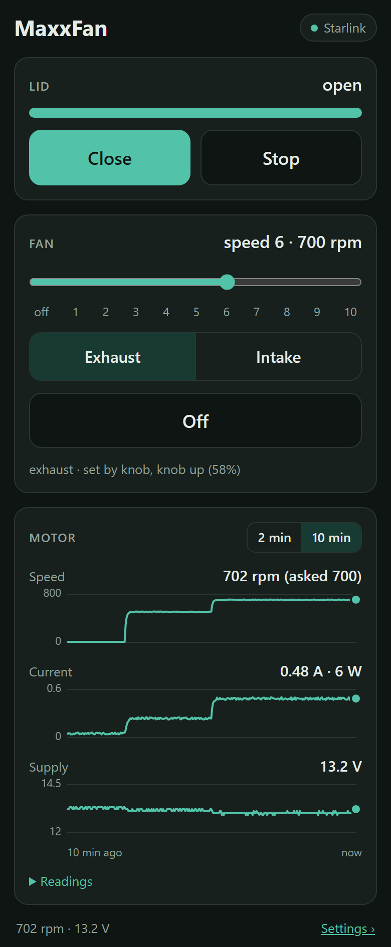
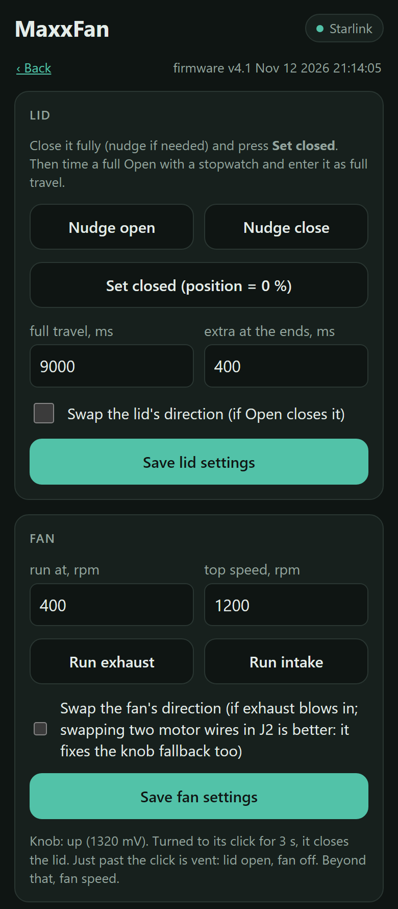
The real page from the firmware (v4.1), drawn with sample readings: it hasn’t run on the new board in the van yet.
The motor
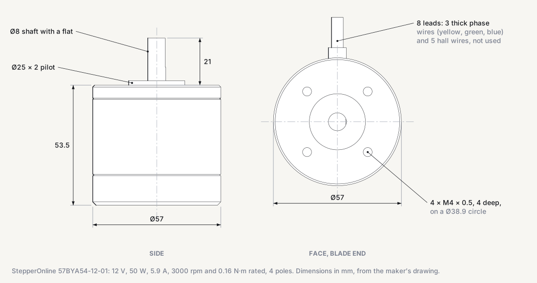
StepperOnline’s 57BYA54-12-01: 12 V, 50 W, 57 mm across and 53.5 mm long. It’s the motor Minuet tuned, and that’s why it’s this one: the motor chip needs a tuning profile for the exact motor, and this one has a proven profile. Minuet runs it quietly from about 100 rpm to over 1200 on the same fan. It needs two adapters: the printed cage, because its screw holes don’t line up with the fan’s motor ears, and a coupler and dowel pin to carry its 21 mm shaft out to the blade (the stock motor’s shaft is 40 mm long).
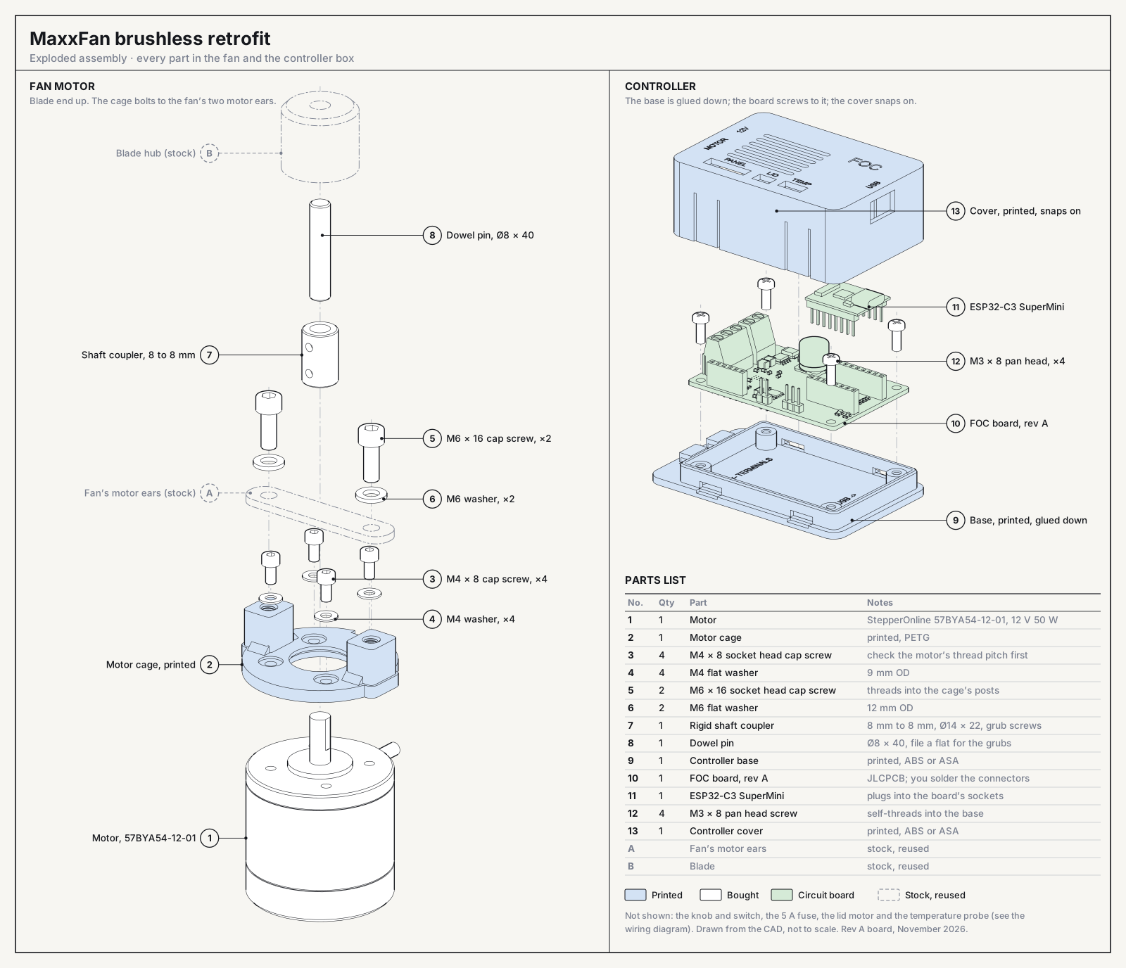
Assembly drawing
Every part, pulled apart along the way it goes together, numbered to match the parts list below. On the left, the fan end: the motor bolts into the cage, the cage bolts to the fan’s two motor ears, and the coupler and dowel pin carry the shaft up to the blade. On the right, the controller: base, board, ESP32-C3 and cover.
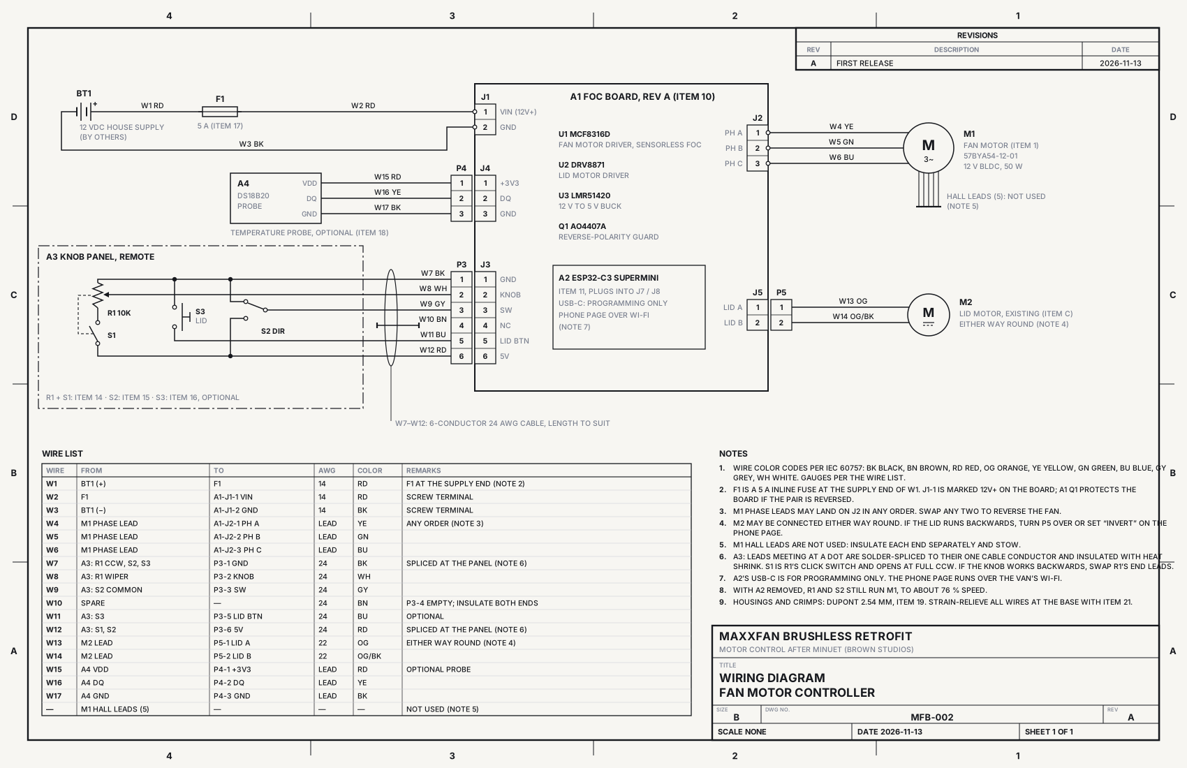
Wiring
Two screw terminals and three plugs. The 12 V feed and the motor’s three phase wires go into the screw terminals at one end of the board; the knob panel, the lid motor and the optional temperature probe plug into its top edge. The USB-C port is only for the first flash.
In the fan
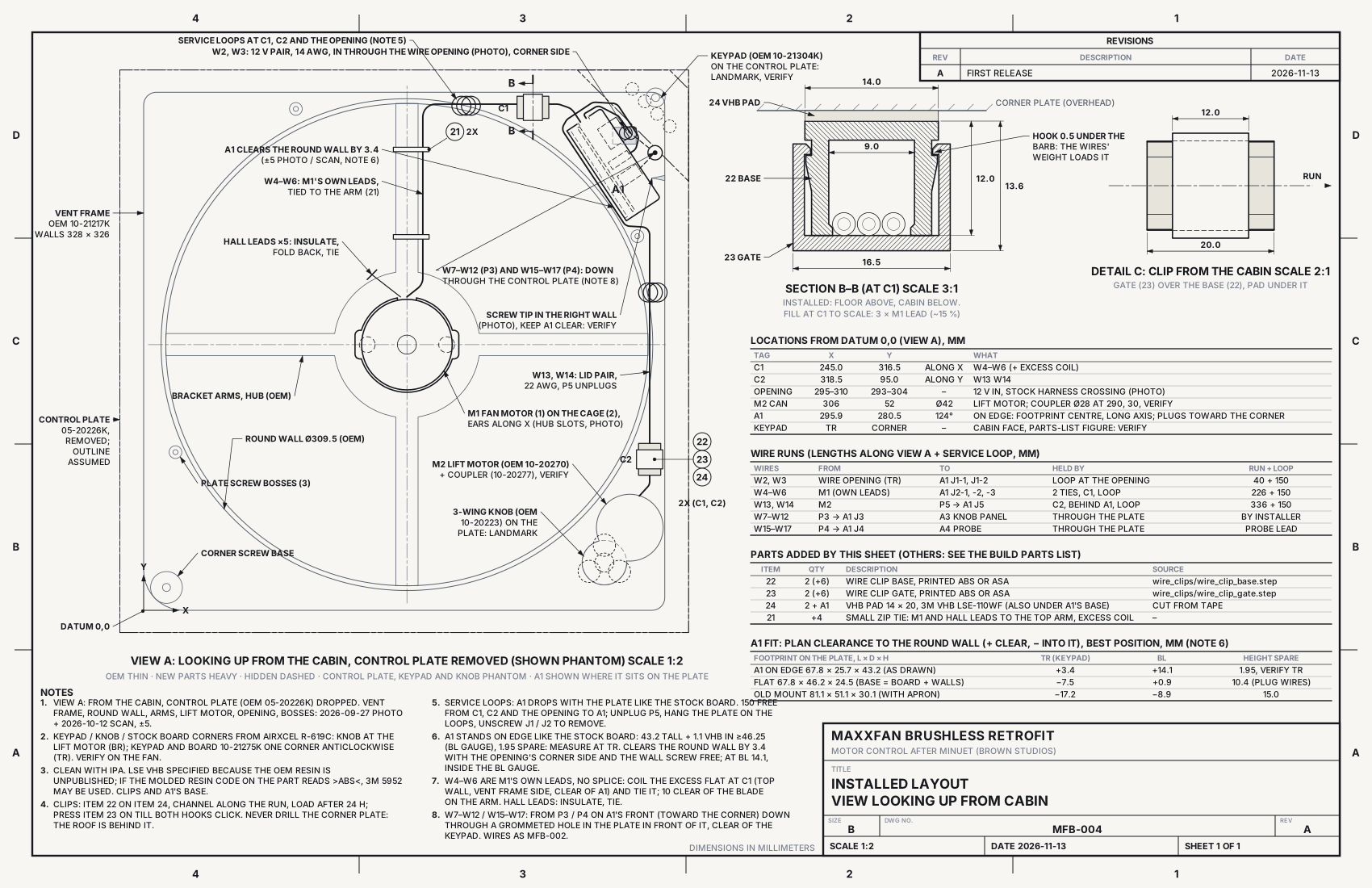
Where everything goes, looking up from inside the van with the control plate off. The board rides on the control plate where the stock board was, so it comes down with the plate; the 12 V pair, the motor’s own leads and the lid motor pair reach it with enough slack to lower the plate. Two printed clips hold the runs up in the cavity, since the fan hangs upside down from the roof.
This sheet is a placeholder. The controller box drawn here is a new slim one that stands on edge, the way the stock board did; it hasn’t been test-fitted yet. The sizes marked VERIFY come from photos and a scan, not a tape measure.
In 3D
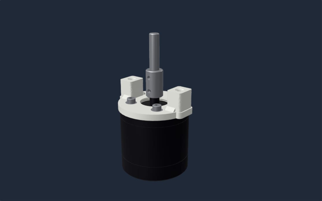
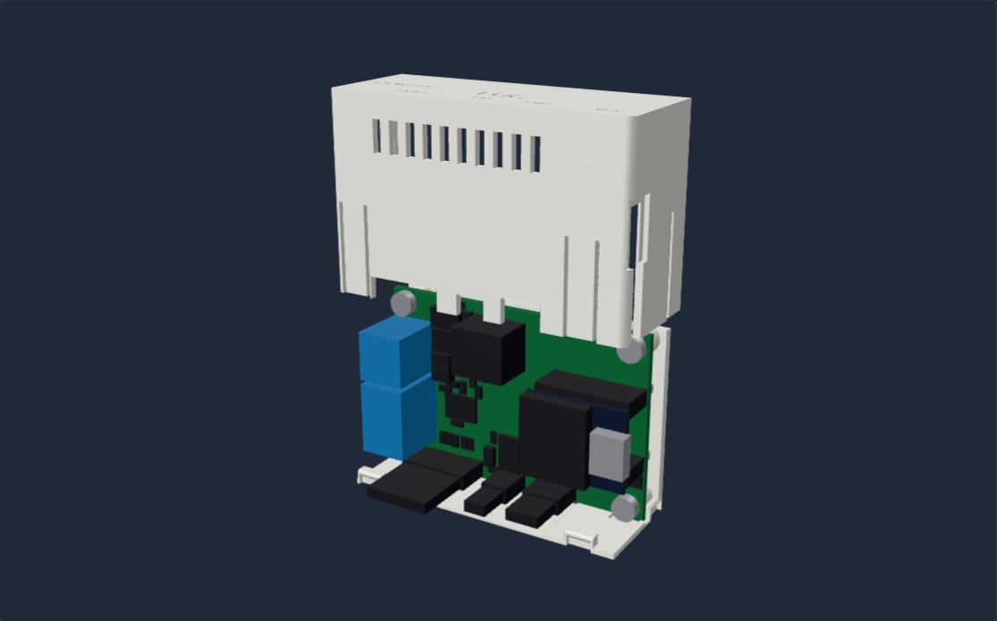
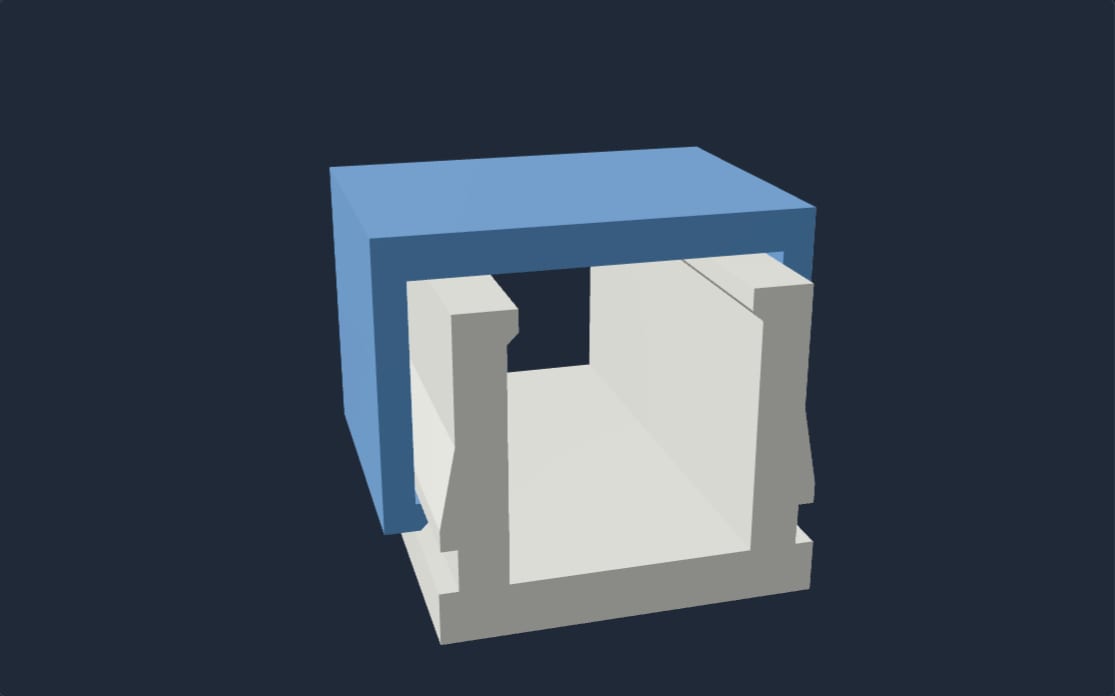
Three of the parts, from the CAD. Each one loads when you ask for it: drag to turn it, and zoom in for the detail.
Parts list
For one fan, numbered as on the drawings.
| No. | Qty | Part | Notes |
|---|---|---|---|
| Fan motor and mount | |||
| 1 | 1 | Motor: StepperOnline 57BYA54-12-01 | 12 V, 50 W brushless. Its hall-sensor wires aren’t used. |
| 2 | 1 | Motor cage | Printed in PETG. |
| 3 | 4 | M4 × 8 socket head cap screw | The maker’s drawing says M4 × 0.5 fine pitch, not the usual 0.7: check your motor before you buy. |
| 4 | 4 | M4 flat washer | 9 mm OD. |
| 5 | 2 | M6 × 16 socket head cap screw | Threads into the cage’s posts. Snug, about 1.5 N·m. |
| 6 | 2 | M6 flat washer | 12 mm OD. |
| 7 | 1 | Rigid shaft coupler, 8 mm to 8 mm | Ø14 × 22 with grub screws (uxcell). |
| 8 | 1 | Dowel pin, Ø8 × 40 | File a flat for the grub screws (uxcell, pack of 10). |
| Controller | |||
| 9 | 1 | Controller base | Printed in ABS or ASA. Sticks to the fan’s control plate, where the stock board sat. |
| 10 | 1 | FOC board, rev A | Order it from JLCPCB with the board files, or ask me for one. |
| 11 | 1 | ESP32-C3 SuperMini | Plugs into two sockets on the board. |
| 12 | 4 | M3 × 8 pan head screw | Threads into the base’s standoffs. |
| 13 | 1 | Controller cover | Printed in ABS or ASA. Snaps on. |
| Controls and wiring | |||
| 14 | 1 | 10k pot with a click switch (B10K) | The knob. Off at the click. |
| 15 | 1 | Two-position switch | Direction: exhaust or intake. |
| 16 | 1 | Push button, optional | Opens and closes the lid. |
| 17 | 1 | 5 A inline fuse and holder | On the 12 V feed, at the supply. |
| 18 | 1 | DS18B20 temperature probe, optional | The three-wire waterproof kind. |
| 19 | 1 set | 2.54 mm DuPont housings and crimps | 1×6 for the panel, 1×2 for the lid motor, 1×3 for the probe. |
| 20 | Wire | 14 AWG pair for 12 V, 22 AWG for the lid motor, 24 AWG for the panel. | |
| 21 | 6 | Small zip ties | Strain relief on the base, and the motor leads on the bracket arm. |
| Wire clips | |||
| 22 | 2 | Wire clip base | Printed in ABS or ASA. Sticks to the vent frame and holds the wires up in the cavity. |
| 23 | 2 | Wire clip gate | Printed in ABS or ASA. Snaps over the base, so the wires’ weight hangs on hooks, not friction. |
| 24 | 3M VHB LSE-110WF tape | For the clips and the controller base. The LSE kind, because Maxxair doesn’t say what plastic the fan is. | |
| Reused from the fan | |||
| A | Motor ears | Part of the fan’s frame. Open the holes to 6.4 mm if the M6 screws don’t pass. | |
| B | Blade | Goes back on the dowel pin. | |
| C | Lid motor | Now driven by the board. | |
The plan, if you want to build one
- Check your fan. This was designed on my MaxxFan, one with the powered lid. The cage is drawn for motor ears 50 mm apart: measure yours before you print it.
- Get the parts on the parts list above. For the board, order it from JLCPCB or ask me for one of mine (below).
- Print the motor cage in PETG, and the controller base and cover and the two wire clips in ABS or ASA.
- Finish and test the board on the bench: solder the sockets, headers and screw terminals (a printed jig holds them), flash the ESP32-C3 from a browser, check the 5 V, then spin the motor before it goes anywhere near the fan.
- Swap the motor: blade and old motor off, new motor into the cage, the cage onto the ears, extend the shaft, blade back on.
- Wire it as on the wiring diagram: 12 V through the fuse, the three motor wires, the lid motor and the knob panel. Route the runs as on the layout, in the clips, with slack to lower the control plate.
- Set it up from your phone: join the van’s Wi-Fi, calibrate the lid, check that exhaust blows out, then save the knob fallback into the motor chip so the knob runs the fan even without the ESP32.
Where it stands
Work in progress. The first boards (rev A) are on order and the firmware for them is written, but it hasn’t run on the new board yet. I’ll update this page as it gets tested, and publish the board files and the printable parts with the first version that has run in my van.
Credit: Minuet
The motor tuning isn’t mine. The MCF8316D setup and the tuned profile for this exact motor come from Jeff Brown’s Minuet, and the chip’s register map from his esphome-mcf8316, both MIT licensed. Minuet is a complete open-source MaxxFan controller that replaces the stock circuit board and keeps the stock keypad and infrared remote: if that’s what you want, start there. This build is a different take on it, with a knob instead of the keypad and plain Arduino firmware with its own phone page.
Boards
Five boards was the minimum order, so I’ll have a few spare. Once mine has proven itself in the van, I’ll pass them on at what they cost me to anyone building one. Get in touch if you’re interested.
Not affiliated with MaxxAir or Airxcel. Changing the motor voids the fan’s warranty, and this is a work in progress: build it at your own risk.
Status
In progress: rev A boards ordered, November 2026
Fits
MaxxAir MaxxFan with the powered lid. Designed on one fan: measure yours first.
Motor
StepperOnline 57BYA54-12-01, 12 V 50 W brushless, sensorless FOC
Board
Rev A, 63 x 42 mm, 4 layers: MCF8316D, DRV8871, ESP32-C3 SuperMini
Power
12 V through a 5 A fuse
Downloads
Code and contact
Project Images